Real-time sonification: Difference between revisions
David Sousa (talk | contribs) |
David Sousa (talk | contribs) |
||
| Line 117: | Line 117: | ||
'''Detailed explanation of the code''' | '''Detailed explanation of the code:''' | ||
The blocks within the '''on start''' block are evaluated sequentially before anything else in the program when the micro:bit is turned on. | The blocks within the '''on start''' block are evaluated sequentially before anything else in the program when the micro:bit is turned on. | ||
Revision as of 18:41, 13 August 2024
Real-time sonification is an exciting technique that can strongly promote students' engagement in STEAM fields. Real-time sonification means that we are not able to perceive the time interval between the acquisition of the data and the respective sound produced by our sonification device because of the speed of the process. Moreover, the methods for creating sound representations of the data are defined simultaneously with data collection (in "real-time").
Before starting, we want to emphasize that the quality of the sound, which is subjective and therefore depends on the user's taste, must be such that at least it does not disturb the user. On the contrary, if it were appealing enough to attract their attention it would be better. On the other hand, when trying to do something "pleasant" there is a risk of generating sound results that do not fulfill the objective of describing the behavior of the input data well. It is therefore necessary to find a compromise: the sound must be sufficiently pleasant as well as exhaustively informative
Real-time sonification devices

To create a real-time sonification device it is useful to use a microcontroller. These are like "small and simple computers" with a single processor unit. They are not computers though. Their architecture is much simpler and they cannot run an operating system. Still, they can be programmed to execute a single program at a time, which can perform multiple tasks but sequentially, according to the order of the instructions listed in the program. There are several types of microcontrollers, the Arduino (arduino.cc) being the most popular.
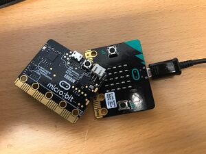
To begin with, the SoundScapes project suggests using the BBC micro:bit microcontroller. This tool is very simple to use, versatile, and includes several embedded sensors readily available to use, eliminating the requirement to build a specific electrical circuit for operation. The micro:bit can be programmed online with Makecode (using the Chrome browser for better compatibility) in python, javascript, or blocks.
Sonification with micro:bit
Before diving into sonification with the micro:bit you must first get familiarized with the Makecode programming environment. On the main page, there are various tutorials, like the "Flashing Heart", the "Name Tag", etc, between which you can choose to get started. If you sign up on the platform, your projects will be saved on your account and you can access them from any device as long as you sign in. Otherwise, they are anyway saved as cookies, however, you can loose them if you clear your browser cache.
Sound notions in micro:bit
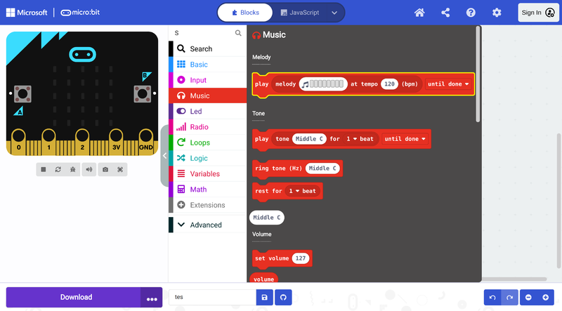
In the Makecode editor, there is a useful and attractive library dedicated to music, especially for young students. This music library offers several commands/blocks that facilitate the generation of sounds and the creation of melodies. There are many blocks and combinations of blocks you can use to generate different kinds of sounds. Here we introduce you to the most basic bocks and progress to more complex examples. It is a good exercise to play with the different blocks and hear what happens to get familiar with them.

Generate a single tone
The following code generates a single tone with a pre-specified frequency Middle C and duration 1 beat when button A is pressed, or a continuous Middle E ring when button B is pressed. It is possible to change the frequency of the tones by clicking the white input fields with values "Middle C" and "Middle E". From the drop-down menu arrows, it is also possible to change the beat duration of the "Middle C" tone and whether the sound is played sequentially with other command blocks, in the background, or in loop [Note 1].
Play a melody
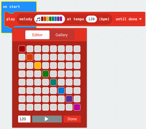
To play a melody use the following block and click on it to create the melody:

The following example code plays two melodies with different bpm values for buttons A and B and stops all sounds when A and B are pressed simultaneously. It is possible to change the melodies by clicking the white input fields with the colorful music notes. As in the previous example, it is also possible to change the beat duration and whether the sound is played sequentially with other command blocks, in the background, or in loop [Note 1].
Manipulate frequency change, waveform, volume and duration
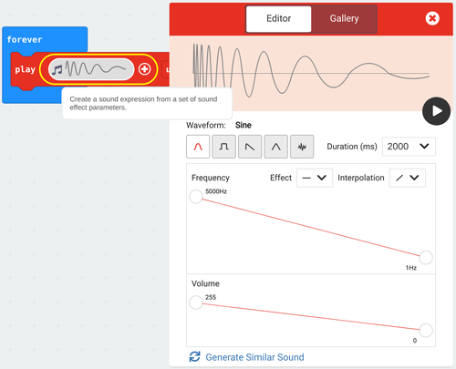
It is also possible to generate more complex sounds by manipulating frequency change, waveform, volume, and duration with the following block:

The following example plays two complex sounds sequentially forever [Note 1]:
Sonification of a Boolean
In computer science, a Boolean, or logical, data type is a fundamental primitive that can hold one of two possible values: true or false, often represented as 1 or 0. To illustrate this concept, we will sonify the simplest data type, the Boolean. Common examples of sensors that produce Boolean data include presence sensors, contact sensors, switches, and buttons.
The following implements the sonification of a Boolean sensor using the micro:Bit, specifically focusing on button A. When the button is pressed, we will hear the note C, and when it is released, the note will change to F. This auditory feedback provides a clear representation of the button's state, enhancing our understanding of Boolean data in a practical context [Note 1].
Detailed explanation of the code:
The blocks are evaluated sequentially from the top to the bottom within the loop block forever which repeats the following evaluation sequence until something stops the program:
- Set the variable X to the button state (true or false whether the button is pressed by the time of the pink block button A is pressed evaluation)
- If the variable/condition X holds true (the button was pressed), ring tone (Hz) Middle C, else, ring tone (Hz) Middle E
Sonification of a range of values (using the micro:bit input sensors)
Most sensors provide a range of values, not just 0 or 1, in which case we must first find out what the lowest and highest possible values are before defining the mapping for sonification. This variable input from the sensor can originate from the light level sensor, the accelerometer, the magnetometer, the intensity of the sound captured by the microphone, or other sensors connected to the micro:bit through the pins. This data can easily be collected by the microcontroller.
Change pith with fixed rhythm
In this example, we show how to map the light level to a frequency range. The internal light sensor of the micro:bit provides a value between 0 (dark) and 255 (very bright). We call this input value variable x. We also define the variables x-Min and x-Max with the minimum and maximum values of our sensor. For the purpose of sonifying the measured light level, we will map the value of the light level to a pitch between 200 Hz (minimum value) and 2000 Hz (maximum value), played at a fixed rhythm [Note 1].
Detailed explanation of the code:
The blocks within the on start block are evaluated sequentially before anything else in the program when the micro:bit is turned on.
- Set the x-Min variable to the light level lowest possible measured value 0.
- Set the x-Max variable to the light level highest possible measured value 255.
The blocks within the block forever are evaluated sequentially in a loop from top to bottom after the on start sequence:
- Set the x variable to the measured light level
- Play a one 1 beat tone with a frequency resulting from mapping the x value (in the x-Min to x-Max range) to the chosen frequency range in the map block.
Change rhythm with fixed pitch
Another option is to maintain a fixed pitch while varying the rhythm based on the light level. We can achieve this by playing a short-duration note and introducing pauses that vary in length, ranging from 1000 ms (for dark conditions) to 20 ms (for very bright conditions). This approach allows for a dynamic auditory representation of the changing light levels [Note 1].
Detailed explanation of the code:
The blocks within the on start block are evaluated sequentially before anything else in the program when the micro:bit is turned on.
- Set the x-Min variable to the light level lowest possible measured value 0.
- Set the x-Max variable to the light level highest possible measured value 255.
The blocks within the block forever are evaluated sequentially in a loop from top to bottom after the on start sequence:
- Set the x variable to the measured light level
- Play a one 1 beat High D tone.
- Pause for a period calculated from mapping the x value (in the x-Min to x-Max range) to the chosen time range in the map block.
Reminder: You can replace the light level input block with any other micro:bit sensor input block (or any other sensors connected to the micro:bit through the pins) that provide a range of values. Just be sure, to redefine the x-Min and x-Max values accordingly, as the accelerometer and the compass heading, for instance, work on a different range.
Multiple inputs mapped to a single sound
Sonification systems often serve to provide more than one piece of information. We can map as many variables as the amount of sound parameters we can control. As long as the sound does not become confusing due to the multiple sound layers playing simultaneously. If we consider that a philharmonic orchestra can have over one hundred elements we have some room for overlaying several sounds. Opposite to the visual stimuli where we cannot exceed a certain number, usually inferior to that of audio stimuli. Finally, like in the orchestra, the sounds have to be carefully arranged together in case of large numbers.
The following sonifies the light level mapped to pith with a pause detefined by the compass heading mapped to milliseconds [Note 1].
Sonification via MIDI (The micro:bit as a MIDI instrument)
The sound produced by the speaker (buzzer) of the micro:bit has little power and does not play low frequencies. The micro:bit is also very limited in its capacity to generate multiple sounds simultaneously and sounds with more complex timbres. In the last example, we used a "trick" to sonify values of multiple inputs. We used the pause (duration of silence between consequent sounds) as a sonification output. Smart but what we would really enjoy would be several sounds simultaneously playing and expressing several layers of data. We can obtain better sound quality and play more instruments at the same time using the midi protocol.
MIDI is a protocol that facilitates real-time communication between electronic musical instruments. MIDI stands for Musical Instrument Digital Interface and it was developed in the early ’80s for storing, editing, processing, and reproducing sequences of digital events connected to sound-producing electronic instruments, especially those using the 88-note chromatic compass of a piano-keyboard. We can roughly, but easily, understand MIDI as the advanced successor of the “piano rolls”, which, more than a century ago, were perforated papers or pinned cylinders, in which music performances were either recorded (in real-time) or notated (in step time). These paper-rolls were then played automatically by specially designed mechanical instruments, the mechanical pianos (pianolas) or music machines, using them as their “program”.
Setup the MIDI
The following video explains in detail how to connect the micro:bit to your DAW (Digital Audio Workstation) or digital synthesizer through MIDI on Windows:
Step-by-step instructions (see the video):
- Install the MIDI Extension for Makecode.
- Create a very basic program using the MIDI extension to test your setup.
- Install Hairless MIDI, open it, and from serial port drop-down menu select the com port (USB port) to which the micro:bit is connected to.
- Install loopMIDI, open it, and click the + button at the bottom-left corner to create a new virtual port.
- Go back to the HairlessMIDI window and on the MIDI out drop-down menu select loopMIDI port
- You might need to unplug and plug in the micro:bit again for it to work.
- You are ready to play!
How it works: The micro:bit sends MIDI messages through serial communication. These messages are then received by Hairless MIDI, which forwards them to LoopMIDI. Acting as a virtual MIDI port, LoopMIDI makes the MIDI messages accessible to computer software/web apps (like DAWs or digital synthesizers) that receive these messages and generate the corresponding sounds, completing the connection.
There are plenty of free (and some open-source, cross-platform) DAW stations like LMMS that you can download and configure to play MIDI input. The easiest method is to play directly from the browser through a web app such as midi.city, the Online Sequencer and many others to discover online. In principle, web apps such as midi.city will readily detect your midi instrument (the micro:bit in this case) and you are ready to play after giving the browser permissions to access your device (which you will be asked to do).
MIDI is a powerful tool for sonification because it allows you to control a wide range of sound parameters, such as pitch, volume, and timbre. This setup allows for multiple Microbits to send MIDI data to a single synthesizer, enabling synchronized sonification of multiple data streams. It also allows a single micro:bit to send MIDI data over multiple MIDI chanels.
Note: On Linux install ttymidi instead of hairlesMIDI and loopMIDI.
Sensor data over MIDI
Previous examples using sensor data can be adapted to send data over MIDI with the Makecode MIDI extension, meaning that the sounds will play not on the micro:bit but through a properly configured computer software/web application. The following example maps the light level to MIDI notes and sends them through MIDI channel 1 [Note 1].
The blocks inside the on start block are evaluated sequentially before anything else in the program when the micro:bit is turned on.
- Show a fancy musical note icon on the LED screen just to make it nicer.
- Set the Instrument_1 variable to midi channel 1. Thus any changes to the variable Instrument_1 are actions on the MIDI channel 1.
- midi use raw serial is what will get the micro:bit to "talk" to the MIDI output device.
The blocks within the block forever are evaluated sequentially in a loop from top to bottom after the on start sequence:
- Set the Note variable to a MIDI note by mapping the light level range of possible values to the chosen MIDI range 40 to 85 (within 0 and 128) using the map block.
- Set the sound volume of Instrument_1 (on MIDI channel 1) to 100.
- Play MIDI note Note (measured light level mapped to MIDI) with Instrument_1 (on MIDI channel 1).
- Pause for 250 ms.
- Stop playing the MIDI note Note.
- Pause for 100 ms.
Using multiple MIDI channels
This example maps the light level to MIDI and uses multiple MIDI channels allowing one to choose to play the notes either with a button or by shaking the micro:bit.
Detailed explanation of the code
The logic behind this example is very similar to the previous one. However, an extra MIDI channel 10 (it could have been any other number between 1 and 16) is set on start as variable Instrument_2. Thus, any changes on this variable are actions on the MIDI channel 10. The mapping of the light level to MIDI is still set within the loop, but the Instrument_1 related blocks and pauses were moved to the input block on button B pressed. The input block on shake just repeats the same code for Instrument_2. Note, that when you play a note, irrespectively of the instrument chosen, a musical note appears and disappears from the LED screen.