Real-time sonification: Difference between revisions
David Sousa (talk | contribs) |
David Sousa (talk | contribs) |
||
| Line 72: | Line 72: | ||
''' | '''Detailed explanation of the code:''' | ||
The blocks are evaluated sequentially from the top to the bottom inside the loop block '''forever''' which repeats the following evaluation sequence until something stops the program: | The blocks are evaluated sequentially from the top to the bottom inside the loop block '''forever''' which repeats the following evaluation sequence until something stops the program: | ||
| Line 79: | Line 79: | ||
# '''If''' the variable/condition '''X''' holds '''true''' (the button was pressed), '''ring tone (Hz) Middle C''', else, '''ring tone (Hz) Middle E''' | # '''If''' the variable/condition '''X''' holds '''true''' (the button was pressed), '''ring tone (Hz) Middle C''', else, '''ring tone (Hz) Middle E''' | ||
=== Sonification of a range of values === | === Sonification of a range of values (using the micro:bit input sensors) === | ||
Most sensors provide a range of values, not just 0 or 1, in which case we must first find out what the lowest and highest possible values are before defining the mapping for sonification. This variable input from the sensor can originate from the light level sensor, the accelerometer, the magnetometer, the intensity of the sound captured by the microphone, or other sensors connected to the micro:Bit through the pins. This data can easily be collected by the microcontroller. In this example, we show how to map the '''light level''' to a frequency range. The internal light sensor of the micro:bit provides a value between 0 (dark) and 255 (very bright). We call this input value variable '''x'''. We also define the variables '''x-Min''' and '''x-Max''' with the minimum and maximum values of our sensor. For the purpose of sonifying the measured light level, we will map the value of the light level to a pitch between 200 Hz (minimum value) and 2000 Hz (maximum value), played at a fixed rhythm. | |||
<HTML> | |||
<div style="position:relative;height:0;padding-bottom:40%;overflow:hidden;"><iframe style="position:absolute;top:0;left:0;width:100%;height:100%;" src="https://makecode.microbit.org/#pub:_MriX6fKfgAj9" frameborder="0" sandbox="allow-popups allow-forms allow-scripts allow-same-origin"></iframe></div> | |||
</html> | |||
'''Detailed explanation of the code''' | |||
The blocks inside the '''on start''' block are evaluated sequentially before anything else in the program when the micro:bit is turned on. | |||
# Set the '''x-Min''' variable to the light level lowest possible measured value. | |||
# Set the '''x-Max''' variable to the light level highest possible measured value. | |||
The blocks inside the block '''forever''' are evaluated sequentially in a loop from top to bottom after the '''on start''' sequence: | |||
# Set the '''x''' variable to the measured '''light level''' | |||
# Play a one 1 beat tone with a frequency resulting from mapping the '''x''' value (in the '''x-Min''' to '''x-Max''' range) to the chosen frequency range in the '''map''' block. | |||
'''Reminder:''' You can replace the '''light level''' input block with any other micro:bit sensor [https://makecode.microbit.org/reference/input input block], or any other sensors connected to the micro:bit through the pins that provide a range of values. Just be sure, to redefine the '''x-Min''' and '''x-Max''' values accordingly, as the [https://makecode.microbit.org/reference/input/acceleration accelerometer] and the [https://makecode.microbit.org/reference/input/compass-heading compass] heading, for instance, work on a different range. | |||
=== Multiple inputs mapped to a single sound === | === Multiple inputs mapped to a single sound === | ||
Revision as of 14:37, 13 August 2024
Real-time sonification is an exciting technique that can strongly promote students' engagement in STEAM fields. Real-time sonification means that we are not able to perceive the time interval between the acquisition of the data and the respective sound produced by our sonification device because of the speed of the process. Moreover, the methods for creating sound representations of the data are defined simultaneously with data collection (in "real-time").
Real-time sonification devices

To create a real-time sonification device it is useful to use a microcontroller. These are like "small and simple computers" with a single processor unit. They are not computers though. Their architecture is much simpler and they cannot run an operating system. Still, they can be programmed to execute a single program at a time, which can perform multiple tasks but sequentially, according to the order of the instructions listed in the program. There are several types of microcontrollers, the Arduino (arduino.cc) being the most popular.
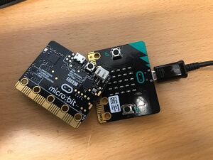
To begin with, the SoundScapes project suggests using the BBC micro:bit microcontroller. This tool is very simple to use, versatile, and includes several embedded sensors readily available to use, eliminating the requirement to build a specific electrical circuit for operation. The micro:bit can be programmed online with Makecode (using the Chrome browser for better compatibility) in python, javascript, or blocks.
Sonification with micro:bit
Before diving into sonification with the micro:bit you must first get familiarized with the Makecode programming environment. On the main page, there are various tutorials, like the "Flashing Heart", the "Name Tag", etc, between which you can choose to get started. If you sign up on the platform, your projects will be saved on your account and you can access them from any device as long as you sign in. Otherwise, they are anyway saved as cookies, however, you can loose them if you clear your browser cache.
Sound notions in micro:bit
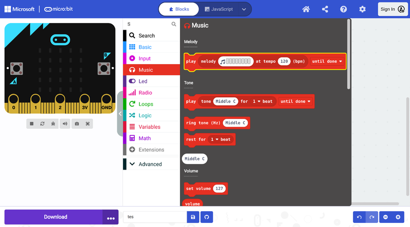
In the Makecode editor, there is a useful and attractive library dedicated to music, especially for young students. This music library offers several commands/blocks that facilitate the generation of sounds and the creation of melodies. There are many blocks and combinations of blocks you can use to generate different kinds of sounds. Here we introduce you to the most basic bocks and progress to more complex examples. It is a good exercise to play with the different blocks and hear what happens to get familiar with them.

Generate a single tone
The following code generates a single tone with a pre-specified frequency Middle C and duration 1 beat when button A is pressed, or a continuous Middle E ring when button B is pressed. It is possible to change the frequency of the tones by clicking the white input fields with values "Middle C" and "Middle E". From the drop-down menu arrows, it is also possible to change the beat duration of the "Middle C" tone and whether the sound is played sequentially with other command blocks, in the background, or in loop [Note 1].
Play a melody
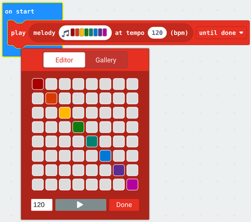
To play a melody use the following block and click on it to create the melody:

The following example code plays two melodies with different bpm values for buttons A and B and stops all sounds when A and B are pressed simultaneously. It is possible to change the melodies by clicking the white input fields with the colorful music notes. As in the previous example, it is also possible to change the beat duration and whether the sound is played sequentially with other command blocks, in the background, or in loop [Note 1].
Manipulate frequency change, waveform, volume and duration
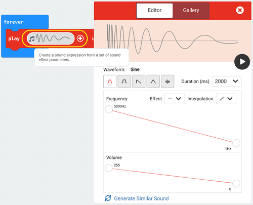
It is also possible to generate more complex sounds by manipulating frequency change, waveform, volume, and duration with the following block:

The following example plays two complex sounds sequentially forever [Note 1]:
Sonification of a Boolean
In computer science, a Boolean, or logical, data type is a fundamental primitive that can hold one of two possible values: true or false, often represented as 1 or 0. To illustrate this concept, we will sonify the simplest data type, the Boolean. Common examples of sensors that produce Boolean data include presence sensors, contact sensors, switches, and buttons.
The following implements the sonification of a Boolean sensor using the micro:Bit, specifically focusing on button A. When the button is pressed, we will hear the note C, and when it is released, the note will change to F. This auditory feedback provides a clear representation of the button's state, enhancing our understanding of Boolean data in a practical context [Note 1].
Detailed explanation of the code:
The blocks are evaluated sequentially from the top to the bottom inside the loop block forever which repeats the following evaluation sequence until something stops the program:
- Set the variable X to the button state (true or false whether the button is pressed by the time of the pink block button A is pressed evaluation)
- If the variable/condition X holds true (the button was pressed), ring tone (Hz) Middle C, else, ring tone (Hz) Middle E
Sonification of a range of values (using the micro:bit input sensors)
Most sensors provide a range of values, not just 0 or 1, in which case we must first find out what the lowest and highest possible values are before defining the mapping for sonification. This variable input from the sensor can originate from the light level sensor, the accelerometer, the magnetometer, the intensity of the sound captured by the microphone, or other sensors connected to the micro:Bit through the pins. This data can easily be collected by the microcontroller. In this example, we show how to map the light level to a frequency range. The internal light sensor of the micro:bit provides a value between 0 (dark) and 255 (very bright). We call this input value variable x. We also define the variables x-Min and x-Max with the minimum and maximum values of our sensor. For the purpose of sonifying the measured light level, we will map the value of the light level to a pitch between 200 Hz (minimum value) and 2000 Hz (maximum value), played at a fixed rhythm.
Detailed explanation of the code
The blocks inside the on start block are evaluated sequentially before anything else in the program when the micro:bit is turned on.
- Set the x-Min variable to the light level lowest possible measured value.
- Set the x-Max variable to the light level highest possible measured value.
The blocks inside the block forever are evaluated sequentially in a loop from top to bottom after the on start sequence:
- Set the x variable to the measured light level
- Play a one 1 beat tone with a frequency resulting from mapping the x value (in the x-Min to x-Max range) to the chosen frequency range in the map block.
Reminder: You can replace the light level input block with any other micro:bit sensor input block, or any other sensors connected to the micro:bit through the pins that provide a range of values. Just be sure, to redefine the x-Min and x-Max values accordingly, as the accelerometer and the compass heading, for instance, work on a different range.